Including Software in the System Reliability Model
A system reliability model that treats software as failure-free hides real risk. Below are the core elements needed to represent software as a genuine contributor to system-level reliability.
Why software has to be in the model, not just the narrative
It's common for a reliability block diagram or fault tree to represent every hardware component in detail while software is mentioned only in a footnote, or assumed perfect. That approach may have worked 40 years ago, but today's system have too much software to ignore. A Reliable Software SOW requires the developer to include the software components on the model in a way that mimics the system.
Software isn't assumed away
To model the system accurately, you cannot treat software as a single monolithic block labeled "Software." If you do, the model assumes that any software failure takes down the entire system, ignoring the architectural boundaries, redundancies, and isolated functions built into the system. Instead, software must be decomposed and mapped directly alongside its corresponding hardware co-elements to reflect true operational dependency
One system-level picture
In a reliability block diagram, for example, a specific software component is modeled in series with the hardware that it supports. For example, the brake system hardware is in series with the brake system software.
Modern safety and mission-critical systems use real-time operating systems (RTOS) that partition software memory and CPU cycles. So, if the infotainment software crashes, a robust architecture ensures it cannot affect the braking software.
Inaccurate Common Cause Failures: A monolithic block implies that a minor glitch in a non-safety task (like a diagnostic logging loop) possesses a 100% mathematical probability of disabling the mechanical brakes.
Kept in step with the design
The model is revisited at each major milestone as the software architecture and code base evolve.
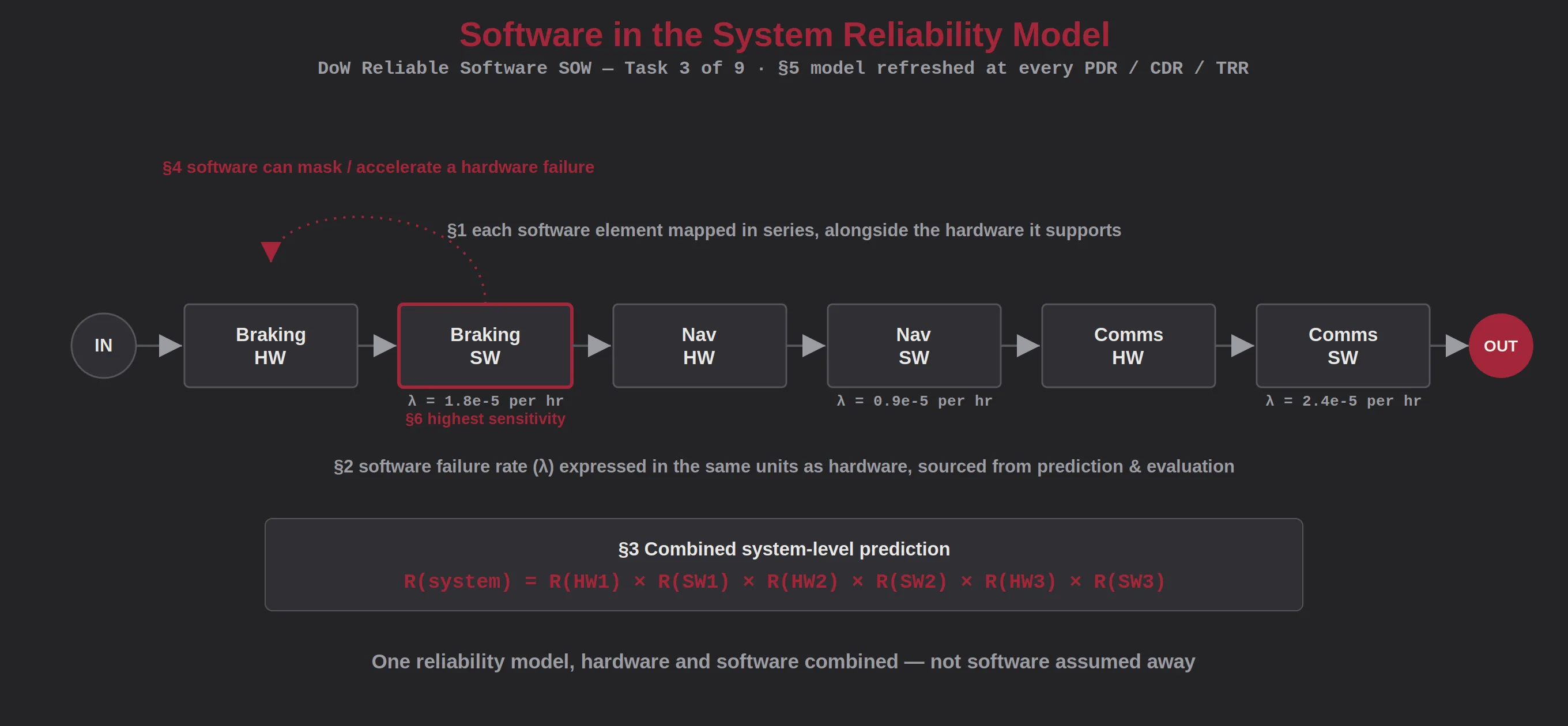
The core elements of software in the system reliability model
Each element below is a step in bringing software into the same reliability model used for hardware, rather than treating it as a separate analysis.
Architecture Mapping
Software elements (CSCIs, services, or components) shall be mapped to the system functions and interfaces they support within the reliability block diagram or fault tree.
- Software components identified alongside hardware in the same model structure
- Interfaces between software and hardware elements explicitly represented
- Mapping kept consistent with the software architecture documentation
- System models include reliability block diagram, fault tree analysis, Markov model, Mission model, etc.
Failure Rate Representation
Software failure rate shall be represented as a model input, using the same units and conventions as hardware failure rate.
- Software failure contribution expressed in reliability model-compatible units
- Values sourced from the prediction and evaluation tasks, not assumed
- Redundancy or fault-tolerance mechanisms in software reflected in the model
Combined Hardware/Software Prediction
The system-level reliability prediction shall combine hardware and software failure contributions into a single, defensible number.
- Documented method for combining hardware and software terms
- System-level prediction traceable to both hardware and software inputs
- Prediction reported as one figure of merit for program reviews
Software-Induced Hardware Failure Consideration
The model shall account for cases where software failures cause, mask, or accelerate hardware failures.
- Known software-hardware interaction failure modes identified
- Cases where software masks a hardware fault flagged for review
- Interaction effects reviewed against the software FMEA
Model Maintenance
The reliability model shall be updated as the software architecture and code mature, tied to major technical reviews.
- Model refreshed at PDR, CDR, TRR, and prior to major test events
- Version history maintained so changes in predicted reliability are traceable
- Updates triggered by significant architecture or requirements changes
Sensitivity Analysis
The developer shall identify which software elements contribute most to system-level reliability risk through sensitivity analysis.
- Ranking of software components by contribution to system failure rate
- Results used to prioritize FMEA, testing, and risk mitigation effort
- Findings reported to program management for resourcing decisions
What modeling software as a real contributor buys the program
A model you can trust
The system-level reliability number reflects reality instead of hiding software risk behind a zero-failure-rate assumption.
Better design decisions
Engineers can see how software architecture choices actually move system-level reliability, enabling real trade-offs.
Focus where it matters
Sensitivity analysis directs FMEA, testing, and mitigation effort toward the software elements that matter most.
A basis for requirements
A combined model gives program management a defensible basis for verifying system reliability requirements at review.
Stop leaving software out of the system reliability picture.
Start with a discussion of your reliability modeling approach.